Large automotive spare parts rarely fit neatly into a standard pallet-storage model. Their dimensions vary, turnover rates are uneven, and many components cannot be placed directly on conventional pallets. At Toyota's spare parts center, large components are stored in steel cages, but those cages are not all the same height.
That difference shaped the warehouse design from the beginning.
Toyota manages nearly 45,000 SKUs across several operating areas. Small components, bumpers, oils, body parts, irregular goods, and large spare parts follow different handling routes. The pallet shuttle area discussed here serves the large-parts section rather than the entire inventory.
A uniform rack design would have been easier to engineer, but it would also have forced every storage level to follow the tallest cage specification. Lower cages would then occupy the same vertical allowance, leaving unused space above them across a large part of the warehouse.
Instead of starting with the robot model, the project team first reviewed the load carriers.
Two cage heights appeared most frequently. The first storage level was therefore planned for cages up to 1,675 mm, while the other four levels were designed around cages up to 1,200 mm. This resulted in a five-level layout with approximately 3,091 pallet and cage positions.
The arrangement is straightforward, but the reasoning behind it is important. In a building with a fixed clear height, storage capacity depends on how closely the rack geometry follows the real load profile. By separating the two main cage heights, the project avoided applying the tallest clearance requirement to every location.
Shuttle Height Became Part of the Storage Calculation
The pallet four-way shuttle used in the project has a body height of 125 mm.
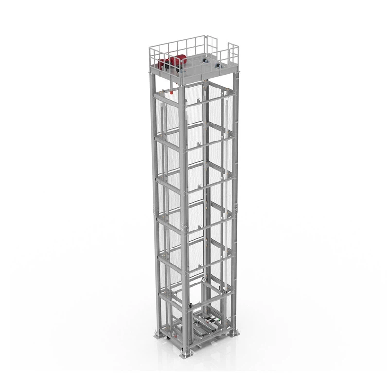
This dimension directly affected the rack design because the shuttle operates below each stored cage. The clearance required for the robot is repeated at every level. A taller machine would therefore consume more vertical space throughout the entire storage structure, not just at one point.
The 125 mm profile reduced the space occupied by the moving equipment and left more of the building height available for inventory.
This worked together with the mixed-height rack configuration. One design choice reduced empty space above the lower cages; the other reduced clearance below every storage level. The final capacity came from combining both decisions rather than relying on a single feature.
The shuttle can handle loads of up to 1,500 kg under suitable project conditions. In actual operation, however, the usable load is determined not only by the robot rating but also by cage strength, weight distribution, rack interfaces, and the way the load is transferred. These conditions were reviewed as part of the system design rather than treated as separate equipment specifications.
Four-Way Movement Created Flexibility, but Scheduling Made It Useful
The large-parts area uses 14 pallet shuttle robots.
Their ability to move between lanes provides more flexibility than a layout in which one machine remains fixed inside one aisle. Even so, four-way movement alone does not guarantee efficient operation.
The robots are managed as a shared equipment pool. When a task is released, the control system checks the location of available robots, open travel routes, pallet lifter status, transfer-point occupancy, and task priority.
The closest robot is not always the best choice. It may be near the target cage but unable to complete the task without waiting for a busy lifter. Sending it immediately could also block a transfer point or delay a higher-priority outbound order.
For that reason, the scheduling logic considers the complete material route rather than only the shortest robot travel distance.
This is particularly important in multi-robot systems. Adding more machines does not automatically create higher throughput. When several robots depend on the same lifter or conveyor interface, poor coordination simply moves the bottleneck from the rack to the handover point.
Toyota's system uses four pallet lifters. Their operation is coordinated with shuttle movements and conveyor tasks so that storage and retrieval can run in parallel while reducing unnecessary queuing.
The Real Bottlenecks Were at the Equipment Interfaces
An inbound cage enters the automated area through a chain conveyor.
Before assigning a location, the warehouse management system checks the cage height, current inventory, storage rules, and task priority. One of the pallet lifters then moves the cage to the required level. An available shuttle collects it from the transfer position and completes the final movement into storage.
For outbound tasks, the sequence runs in reverse. The shuttle retrieves the requested cage, transfers it to the lifter, and the cage then moves through the conveyor interface to the next operating area.
On paper, this process appears simple. In practice, most waiting occurs where one machine hands a load to another.
A shuttle may arrive at the lift quickly but remain idle because the lift is completing another task. A lifter may reach the conveyor level but be unable to release the cage because the downstream station is still occupied.
This is why shuttle speed, lift capacity, and conveyor flow were not calculated independently. The project team checked the interfaces against the same inbound and outbound process, with particular attention to where tasks could queue during peak periods.
The system's operating performance therefore depends less on the headline speed of one device and more on whether robots, lifters, and conveyors can complete each handover without creating repeated waiting.
Warehouse Data Had to Follow the Same Route as the Cages
The physical system was only one part of the project. Toyota also needed business orders, inventory data, equipment tasks, and material movements to remain connected.
DELIECN's WMS interfaces with Toyota's TOPSS sales system and an upstream warehouse platform. Information received from those systems is converted into warehouse instructions covering inbound storage, replenishment, retrieval, and outbound handling.
The WCS then breaks each warehouse instruction into equipment actions.
A retrieval request may require a shuttle to reach the cage, move it to the correct transfer point, wait for a pallet lifter, change levels, and then release the cage to the conveyor. Each action needs to be completed and confirmed before the process continues.
This gives warehouse operators more than a final inventory figure. They can see where a cage is stored, whether a task has started, which piece of equipment is currently executing it, and where a delay has occurred.
That visibility becomes increasingly important when several robots and lifters are working at the same time.
What Changed in the Large-Parts Area
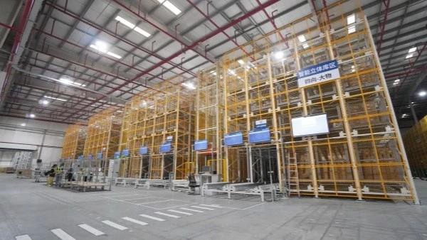
The completed storage area includes five rack levels, approximately 3,091 pallet and cage positions, 14 shuttle robots, four pallet lifters, chain conveyor connections, and coordinated warehouse software.
The first level serves cages up to 1,675 mm high. Levels two through five accommodate cages up to 1,200 mm.
The lower shuttle profile preserved more usable vertical space. The two rack-height specifications reduced clearance that would otherwise have remained unused. Shared robot scheduling made it possible to distribute tasks according to actual workload instead of reserving one machine for each aisle.
These improvements belong specifically to the large-parts area. Toyota's wider warehouse automation project also covered small-parts storage, inter-zone transportation, and other handling processes.
Across the complete project, Toyota's internal supply cycle was reduced from eight days to two days. That result should not be attributed to the pallet shuttle area alone. It came from coordinated changes across storage, picking, transportation, and information management.
The more practical lesson from the large-parts section is that capacity and flexibility were created by several linked engineering decisions.
Rack heights followed the actual cage dimensions. Shuttle geometry was treated as part of the vertical storage calculation. Robot quantities were assessed together with lift capacity and conveyor interfaces. Software rules were built around the same physical limits used in the equipment design.
For automotive spare-parts warehouses, this planning approach is often more valuable than choosing the fastest shuttle or installing the largest possible robot fleet. The system performs well only when the loads, racks, transfer equipment, and task logic are designed around the same operating reality.